
The first thing to consider when installing your 3D seismic sensor is location. This sensor is very sensitive to all vibration sources. Try to locate the sensor as far away as possible from local vibration sources that vibrate the ground such as motors, machinery, farm equipment, houses, buildings, roads, highways, and railroads etc.
Check that the signal cable is long enough to reach between the InfraSignal Radio or the Thru-The-Wall cable adapter and the 3D seismic sensor. If not long enough, consider purchasing a longer cable from InfraSignal Radio and return your shorter cable. Custom cable lengths up to 1000 feet in 50-foot increments are available. Before returning your shorter cable, contact InfraSignal Radio, LLC for an RMA (Return Material Authorization) number.
Call 1-8 His Signal (1-844-774-4625) or write to us using the Contact Us form.
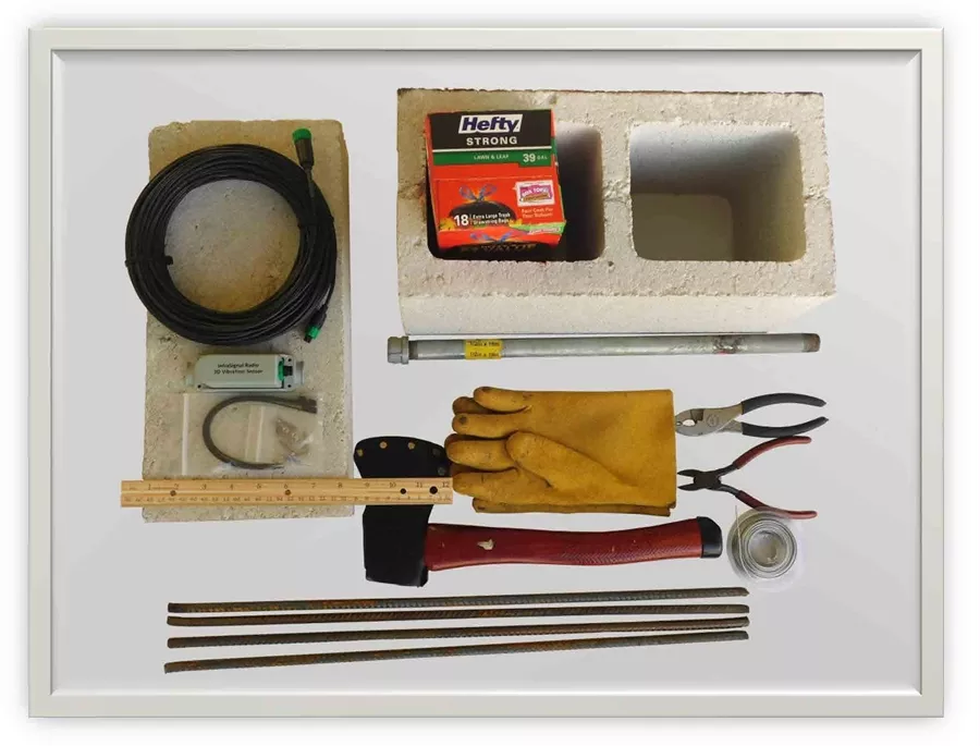
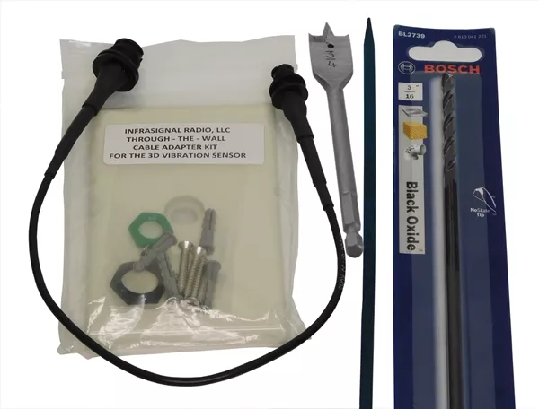
The following information can be used to install your 3D seismic sensor. All the hardware items used can be purchased at Home Depot, Lowes, Ace Hardware and/or other similar stores.
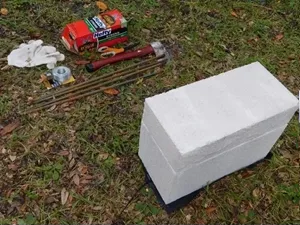
The following is a list of items and tools that can be used with this installation. Other items and tools may be needed if different installation methods are used.
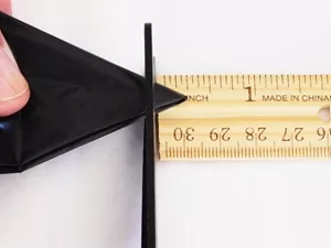
The 1.1mil thick plastic sheet is used as a moister barrier. If you use a large trash bag, cut it open. Make a small hole in the middle by folding in half, then fold it in half again, then fold the folded square corner a third time. Using the scissors, cut 3/8” off the corner that was made when you folded the plastic sheet three times. That will leave an octagon shaped hole about ¾” across in the plastic sheet to drive the water pipe (ground stake) through.
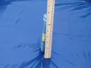
Lay the plastic sheet out flat at the location you have chosen for the 3D seismic sensor. Drive the ground stake through the hole and straight (not leaning over) into the ground, leaving 7 inches from firm ground sticking up.
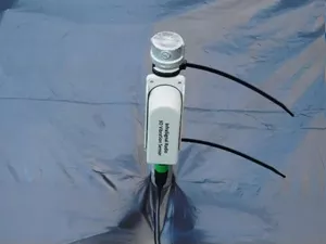
Attach the 3D seismic sensor high on the ground stake, just under the end cap, using 2 of the provided cable ties. The green signal connector should be pointing down. Pull the cable ties tight and cut the excess off using the side cutters. Connect the cable to the sensor using the small green cable connector. Make sure the green locking nut on the cable is locked to the green sensor connector. Sometimes it takes a very hard twist to get it to lock. Roll out several feet of cable while being careful to avoid twist and kinks.
CAUTION: Do not drive the ground stake further into the ground after attaching the very sensitive seismic sensor. Remove the sensor, drive the ground stake further into the ground, then re-attach the sensor.
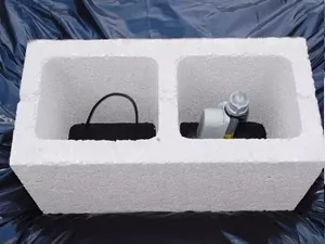
Smooth out the plastic sheet and carefully place the two-hole concrete block around the sensor and ground stake as shown. The cable is routed under and held down by the center section of the concrete block. While the cable in the other hole should have a loop. This loop provides some isolation from vibrations in the event that the cable gets tripped over or jerked. Consider burying the cable 2 or 3 inches in exposed areas.
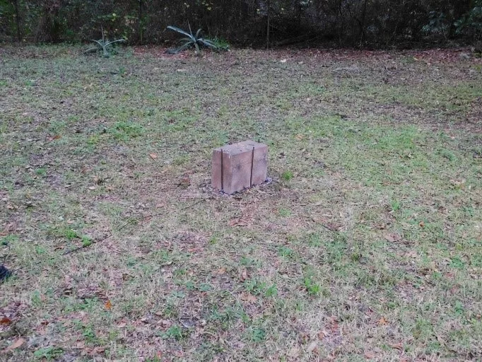
Place the 16”x8”x4” solid concrete block on top of the 2-hole concrete block. Using the scissors, trim the excess plastic sheet around the concrete blocks. Be careful not to cut the outer cover of the signal cable. Any cut could allow moisture to seep in and over time ruin the cable.
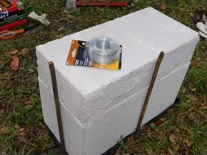
Using your hammer or small axe, drive the four steel rebar stakes into the ground, around the concrete blocks as shown in the picture. These stakes should be tight against the bottom of the concrete blocks. Leave about 1 inch of the stakes sticking up above the concrete blocks. This will allow the stakes to be pulled up tight against the top of the concrete blocks using steel wire. With the stakes being tight against the bottom of the blocks and the steel wire pulling the stakes tight at the top of the blocks will help to keep the blocks from moving in the event that something bumps into them.
Using the pliers, wrap the steel wire from one ground stake to another while pulling the wire tight so the stakes are tight against the concrete blocks as shown.
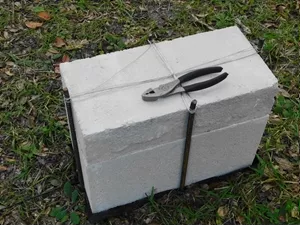
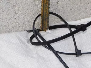
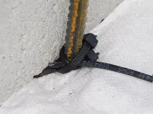
Anchor the signal cable to the steel rebar ground stake to prevent the cable from being pulled out in the event someone trips over it. Place 2 cables ties around the cable and ground stake as shown in the picture. The 2 cable ties want to be crisscrossed so the cable enters and exits at the same angle with the ground.
The cable ties want to be snug but not tight to prevent damage. Cut off the excess cable ties with the side cutters.
If the 3D seismic sensor installation is an eyesore, consider camouflaging it with indoor/outdoor spray paint.
Test the system. Finish “Rolling” out the cable, making sure there are no kinks or twists. Connect the cable to the radio and turn the radio on. Go to the OPTIONS page and touch the FAST IMPULSE RESPONSE button, then the DETECT PULSE button and finally the DETECT PULSE ON CHART button.
Go out to the 3D seismic sensor installation. Start by standing 5 to 10 feet away and stomp the ground a couple of times. The distance from the sensor installation will vary widely depending on the soil, how heavy you are and how hard you stomp. The alarm should sound.
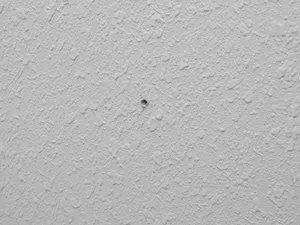
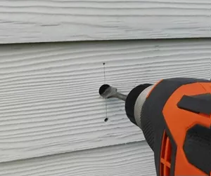
Locate a spot for the inside connector face plate. The pilot hole should be about 15” high from the floor and in between studs. Use a stud finder to avoid electrical wires and pipes. Use the 12” long 3/16” drill bit. Drill straight and level all the way through the wall.
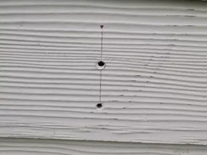
Draw a vertical line, up and down through the pilot hole. Use the inside face plate as a templet and mark the upper and lower inside screw holes. Use the 3/16” drill bit for the inside screw holes. Use the ¾” spade drill bit to drill the cable hole. Drill both just through the inside wall. DO NOT drill all the way through the wall.
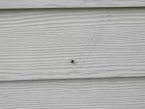
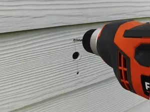
The original pilot hole came out low in this installation. When possible, holes that are too high or too low to use for the cable hole, consider it a screw hole for the face plate. When it’s not possible, consider filling it with putty, (not supplied).
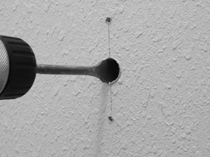
Draw a vertical line through the pilot hole. Use the inside face plate as a templet and mark the positions for the cable hole and the second screw hole. Drill a pilot hole through the outer wall middle mark just deep enough for use by the ¾” spade drill bit.
Use the ¾” spade drill bit to open up the cable hole. If the wall is rock, brick, or cement a masonry drill bit (not supplied) may be needed.
Drill the top face plate screw hole. If the wall is soft wood, use just the 3/16” drill bit. If the wall is hard, use a 13/64” drill bit to further open up the 3/16” hole.
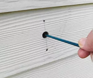
Use the 15” dowel or 12” long drill bit to open up a hole through the insulation large enough to pass the cable and small connector through. In this case, aim down a little bit, because the original pilot hole is lower than the cable hole.
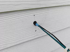
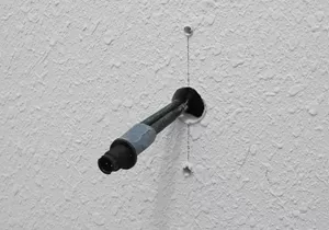
Tape the pointed end of the dowel to the back end of the small cable connector. Push it through to the inside.
Remove the tape and dowel.
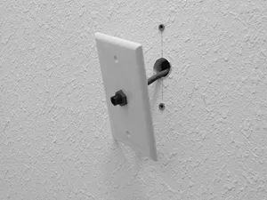
Install the screw anchors in the 3/16” holes. Attach the inside face plate to the cable connector. The rubber gasket should be on the back side of the plate. Tighten the green nut up snug by hand or use a 5/8” socket wrench by hand. Do not over tighten.
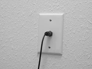
Screw the face plate to the wall and attach the 12’ signal cable.
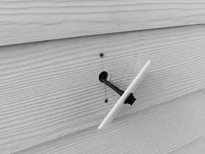
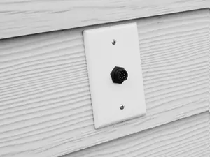
Mount the outside face plate to the cable end with the larger connector. The rubber gasket should be on the back side of the face plate. Tighten the green nut up snug by hand, or use a 13/16” socket by hand. Do not over tighten.
Consider sealing up the cable hole with putty (not supplied) before attaching the cable and face plate to the outside wall.
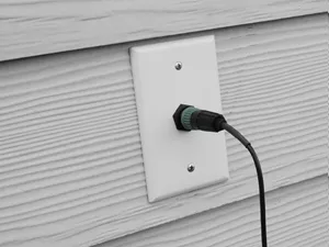
Align the connectors keys and push together. There is an O-ring seal in the cable connector, so push snug and twist to the right. That’s it. You’re finished.
In the future, if you wish to relocate the THRU-THE-WALL cable adapter, simple remove it and replace it with blank face plates. Blank face plates are available at Lowe’s, Homes Depot, Ace Hardware and other similar stores.