All Radio Modes
Detect Early Signs of a Developing Landslide
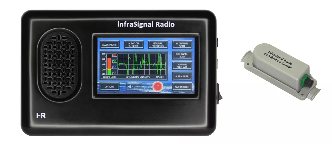
When the radio is used with a seismic (ground vibration) sensor, it can detect the early signs of a developing landslide. The United States Geological Survey (USGS), Federal Emergency Management Agency (FEMA) and Center for Disease Control (CDC) websites report lots of warnings signs before a landslide occurs. All of these warning signs involve small movements and vibrations in the ground. See (MUD, ROCK, LANDSLIDES).
It can also detect extremely weak seismic vibrations from other dangerous local sources such as Rock Slides, Mudslides, Flash Floods, Tsunamis, Earthquakes, Volcanoes and Tornadoes touching the ground.
This is the mode recommended for homeowners. In this display the scope shows a rambling and noisy signal from the 3D seismic sensor and the signal level bar graph shows an extremely strong signal level. A signal level of this magnitude would only be seen in extreme and dangerous conditions.
When the signal level first turns red, it’s a sign that a landslide might be developing. If it continues, evacuate immediately.
To set the system up to detect dangerous ground (seismic) vibrations from local sources, first, take note of the level on the SIGNAL LEVEL bar graph, then go to the OPTIONS page. Ensure that the ALARM IS ENABLED, then go to FAST AGC (Automatic Gain Control). FAST AGC will appear in the CURRENT AGC SETTINGS window. Then go to INFRASIGNAL ON CHART or GO BACK TO MODE >> ADJUSTMENTS and adjust the red ALARM threshold to just above the signal level you took note of on the SIGNAL LEVEL bar graph. Then go back to the INFRASIGNAL ON CHART or SCOPE. The alarm threshold is shown numerically and by the two red markers, one on each side of the green/yellow/red signal level bar graph. This may require several tries (ADJUSTMENTS page – MODE page – ADJUSTMENTS page etc.) before reaching the “no faults alarms” level.
If you get short burst of vibrations occasionally, try to identify the source and determine if they are benign. If they are not dangerous, the settings may be better if you set OPTIONS >> NORMAL AGC >> INFRASIGNAL ON CHART or GO BACK TO MODE and don’t use the FAST AGC option.
Every location and installation are different, so only local trial and error can determine the proper adjustments and settings to prevent faults alarms and yet be sensitive enough to detect very early rumbling of dangerous ground.
Detect Pulse on Chart
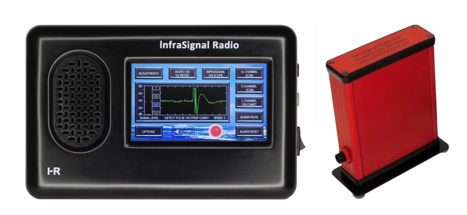
This is the normal mode used by those concerned with EMP. This mode is used with the Nuclear & Solar EMP Sensor to detect both sources of EMP.
In this display the strip chart shows a pulse that sounded the alarm immediately when it first appeared on the edge of the screen. Unlike the alarm system setup to monitor for ground vibrations, the EMP Sensor setup does not require adjustments of the ALARM threshold. The EMP Sensor alarm setup works strictly with a magnetic pulse as seen on the DETECT PULSE ON STRIP CHART screen above.
The EMP Sensor components are housed in an aluminum shield and do not respond to a voltage signal, only a magnetic variation such as a magnetic pulse. The signal level as seen on the SIGNAL LEVEL bar graph to the left will always be low except during a varying and prolonged Electromagnetic Pulse, (EMP).
To setup the system to detect a nuclear or solar EMP, go to OPTIONS >> NORMAL AGC >> FAST IMPULSE RESPONSE >> DETECT PULSE buttons. A red-letter P will appear in the CURRENT AGC SETTINGS window. This red-letter P indicates that the radio is setup to detect a fast pulse and sound the alarm. Select the DETECT PULSE ON CHART or the INFRASIGNAL ON CHART button. To monitor the system you can also use the INFRASIGNAL ON SCOPE mode. The system is now set up.
When an EMP is detected while using the detect pulse option, it is saved to nonvolatile memory very fast before the system loses sufficient power. When power is restored, (perhaps with a generator or backup battery) the alarm will sound and show a message that says “A pulse was detected before loss of power. To reset the alarm, go to OPTIONS >> ALARM TEST >> ALARM RESET”. This ensures that you are alerted to a NUCLEAR or SOLAR EMP and power loss, the two events occurring together.
The only way that this alarm condition can be reset, that is, when using the detect pulse option and after power is lost and then restored, is for a person to use the special sequence to reset it (go to OPTIONS >> ALARM TEST >> ALARM RESET). This special reset sequence is designed to prevent younger members of your crew from accidentally resetting it without your knowledge. They can easily mute the alarm sound, but unless they can read, it would be very unlikely they could reset the alarm.
When a less than severe NUCLEAR or SOLAR EMP occurs and the power is not lost, the alarm will sound until it’s reset. In this case, resetting the alarm is normal and does not require the special sequence.
16 Channel Scan - Multiple Signals
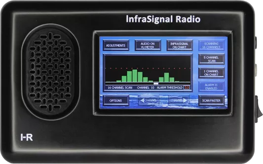
This is the mode to use when you want to detect a signal that is mixed in with other signals as might be observed when using one of the wide-band infrasignal modes.
The radio can process infrasignals from several sources, such as infrasonic microphones, infrasonic hydrophones and extremely large loop antennas, all of which can contain multiple signals. This mode scans the frequency range of 1 Hz to 30 Hz in 16 channels and uses narrow band filters to separate the signals. This mode can be used with or without the alarm function turned on.
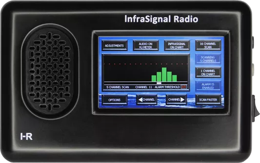
In this display, if the alarm function were turned on it would alarm if either one or both signals were to cross the alarm threshold level. See more details in the 16 CHANNEL SCAN – ONE SIGNAL paragraph.
16 Channel Scan - One Signal
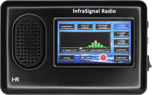
In this display, the alarm function is turned on and a relative strong test signal is used.
In this case it was detected and peaked in channel 12. When the signal level approaches the alarm threshold (red dotted line), it turns yellow. When it crosses the alarm threshold the first time the signal level turns orange and pauses for a few seconds to take a second measurement. If the signal level crosses the alarm threshold durning the second measurement, it will turn red and sound the alarm. Making a second measurement greatly reduces the chance that a noise spike will cause a false alarm.
5 Channel Scan
Occasionally you may want to watch for an infrasignal who’s frequency you’re not quite sure of. You don’t want to scan the whole frequency band, because it takes over one and a half minutes to scan the 16 channels and you might miss an abrupt signal.
First, determine the channel number of the frequency you’re not quite sure of. Touch the OPTIONS >> USER GUIDE buttons. Go to PAGE 5. In the paragraph “5 CHANNEL SCAN.” there is a list of channel numbers and corresponding upper and lower frequencies. Select the channel number that most likely covers the right frequency. Touch the GO BACK TO MODE >> 5 CHANNEL SCAN mode buttons, if not already selected. Then use the left <CHANNEL or right CHANNEL> buttons and continue to touch until the channel number indicated on the status bar is the one you selected from the list.
The scan will start on the channel you selected. It will scan to the right, then scan to the left, back and forth across the five channels. You can speed up the scan by touching SCAN FASTER, but with a tradeoff. The signal strength measurement may not peak as strong and you may miss a very weak signal.
When an infrasignal appears in a channel off to one side of center, the scan can be adjusted using the left <CHANNEL or right CHANNEL> buttons.
To monitor the infrasignal, touch the 1 CHANNEL ON CHART button when the proper channel number appears on the status bar. To measure its frequency, touch 1 CHANNEL ON SCOPE >> MEASURE FREQUENCY.
Audio on VU Meter
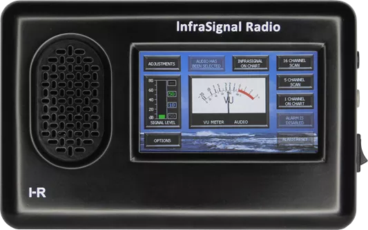
The InfraSignal Radio has a regular audio mode. This mode is very useful when used with an infrasound microphone or an infrasound hydrophone whose frequency response also covers the audio frequency range.
Assuming you are monitoring an infrasound signal using one of the non-scanning modes i.e., INFRASIGNAL ON CHART, INFRASIGNAL ON SCOPE, 1 CHANNEL ON CHART, 1 CHANNEL ON SCOPE or FREQUENCY MEASUREMENT. You can switch to AUDIO ON VU METER to see if you hear a sound with the same rhythm.
This can help you identify the source of the infrasound. You can measure the frequency of this infrasound by using the procedure described in the MEASURE FREQUENCY paragraph. The ALARM function is not available in the AUDIO ON VU METER mode.
ON the right side of the radio is an ON/OFF power switch and two (2) phone jacks. These phone jacks, by design, require a more than usual amount for insertion force.
The top (black) phone jack outputs the infrasignal at a fixed level. This output is provided for recording and/or monitoring on a video display. When using the AUDIO ON VU METER mode, regular audio can be heard from this jack at a fixed level. This output is quite loud in most headphones.
The bottom jack (gray) provides regular audio and tone adjusted transformed infrasignal audio. The audio level from this jack is adjustable with the volume control. When a headphone is plugged into the audio phone jack, it disconnects audio from the speaker. It does not disconnect alarm sound from the speaker and alarm sound is not heard in the headphones.
Measure Frequency
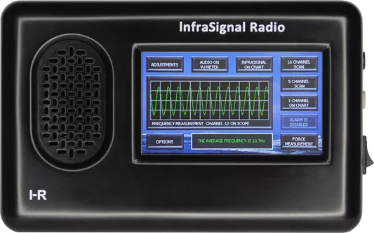
Measuring the frequency of a strong signal in one of the infrasignal modes is easy. Touch the INFRASIGNAL ON CHART >> INFRASIGNAL ON SCOPE >> MEASURE FREQUENCY buttons. The radio takes a sample of the signal and displays the frequency in green text in a window at the bottom of the screen.
If the signal strength decreases and a message appears in the window “WAITING FOR A STRONGER SIGNAL”, you can touch the FORCE MEASUREMENT button. This allows frequency measurements to be made all the way down to the noise level. The frequency measurements will be displayed in yellow text to indicate that the measurements are less accurate.
When the signals are not strong, it is recommended that frequency measurements be made using the 1 CHANNEL mode. The first step is to determine which channel displays the strongest signal. Touch the 16 CHANNEL SCAN button and make a full scan.
When you see which channel has the strongest signal, touch the 5 CHANNEL SCAN button and use the left CHANNEL button to back up. After the scan starts again and pauses in the channel with the strongest signal, touch the 1 CHANNEL ON CHART >> 1 CHANNEL ON SCOPE >> MEASURE FREQUENCY. The display will change to show the signal on the scope and an accurate frequency measurement in green text in the window below the scope.
Again, you may want to measure the frequency of a much weaker signal that falls below a level that ensures an accurate measurement. As before, a message appears in the frequency measurement window, “WAITING FOR A STRONGER SIGNAL”. Touch the FORCE MEASUREMENT button. The message disappears. The text in the frequency measurement window will turn yellow to indicate that the frequency measurements will be less accurate as those with the stronger signal.
1 Channel on Chart / Scope
The 1 Channel on Chart / Scope are InfraSignal Radio’s most sensitive modes. Under test conditions, signals in the range of 2uv to 3uv (microvolts) have been detected.
To monitor signals using these modes you must first select the channel you want to monitor. You can go to 16 CHANNEL SCAN or 5 CHANNEL SCAN and use the <left CHANNEL or right CHANNEL> buttons. When the channel number you want to monitor appears on the status bar, touch the 1 CHANNEL ON CHART button. The screen will change to show the SIGNAL LEVEL bar graph and the signal on the STRIP CHART window.
If you prefer, you can touch the 1 CHANNEL ON SCOPE button and monitor the signal on the scope display. You can touch the same located button again (MEASURE FREQUENCY) and measure the signal’s frequency. More detailed information is covered in the MEASURE FREQUENCY section.
Scan 16 Test Signal
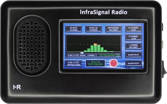
There are four (4) BUILT-IN-TEST “BIT” in the InfraSignal Radio. They are SCAN 16 TEST SIGNAL, SINE WAVE TEST SIGNAL, ALARM TEST and FREQUENCY MEASUREMENT test.
To run these tests, go to the OPTIONS page. All of these tests are located in the lower right corner of the page. If you start with the SCAN 16 TEST SIGNAL test, the button will change to the SINE WAVE TEST SIGNAL test. The FREQUENCY MEASUREMENT test results are displayed at the bottom of the SINE WAVE TEST SIGNAL screen.
Except for the ALARM TEST, for best results, turn the radio off then disconnect the sensor from the radio. This can be done at any cable connection between the sensor and the radio. Turn the radio on and go back to the OPTIONS page. The SCAN 16 TEST SIGNAL and the SINE WAVE TEST SIGNAL are both system level test. That is, a signal from a built-in signal generator is fed into the signal input of the radio and goes through the entire system. The result is displayed on the screen.
The SCAN 16 TEST SIGNAL is the first test to run when you want to test the radio’s performance. During this test, the radio will scan the 16 channels. As it approaches the middle of the screen, increasing signal strengths will be observed on the bar graphs. As it progresses, the signal strengths will increase until it reaches the center channel and crosses the test required green dotted alarm threshold. At this point the scan will pause and take a second measurement. If the second measurement crosses the green dotted alarm threshold, the alarm will sound. The red light will flash and a green message will appear at the bottom of the screen, “BUILT-IN TEST PASSED”.
If the scan completes the full 16 channels and the signal strengths do not cross the test required green dotted alarm threshold, a red message will appear at the bottom of the screen “SYSTEM TEST FAILED”.
At any time during this test, you can go to SCAN 16 TEST INSTRUCTIONS for more information. Touch the BACK TO SCAN 16 TEST button to return.
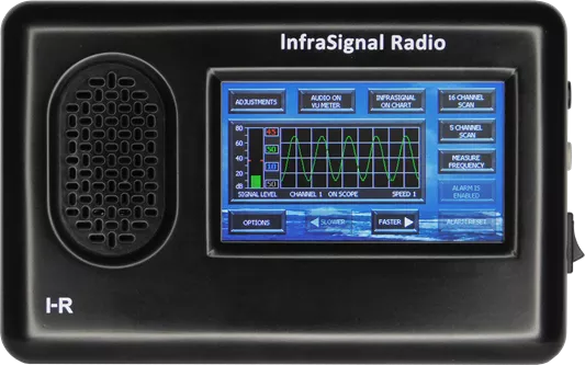
Sine Wave Test Signal
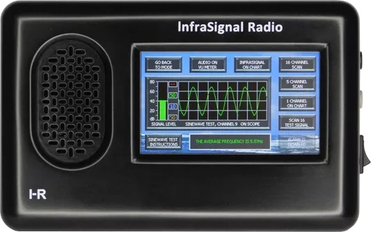
The SINE WAVE TEST SIGNAL test is the second system level test to run when you want to check the radio’s performance.
Touch the SINE WAVE TEST SIGNAL button as soon as you see the number 9 appear on the status bar. The screen will change to show the SIGNAL LEVEL bar graph and scope display. The signal level should be even (+/- 2 pixels at room temperature) with the top of the two green markers. If so, the radio signal sensitivity part of the test has passed.
A sine wave will show on the scope and you will hear the transformed infrasignal. At the bottom of the screen is the FREQUENCY MEASUREMENT window. The average frequency measurement should read between 5.4Hz and 5.7Hz, if so, the sine wave frequency measure test has passed.
At any time during this test, you can touch the SINE WAVE TEST INSTRUCTIONS button for more information. Touch BACK TO SINE WAVE TEST to return.
Adjustments
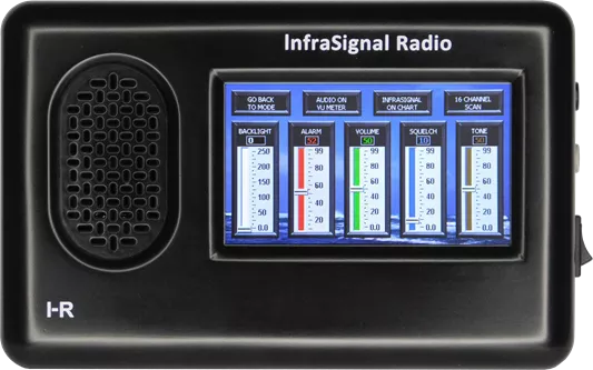
The adjustments page has 5 slider type adjustments, BACKLIGHT, ALARM, VOLUME, SQUELCH and TONE.
The BACKLIGHT adjustment controls the brightness of all parts of the screen. The screen can easily be seen in bright sunlight. When the InfraSignal Radio is battery operated, reducing the BACKLIGHT will increase the battery life.
The ALARM adjustment controls the alarm threshold. Its value is displayed on the sliding scale and also displayed numerically in red above the sliding scale. The value is also displayed at the top of the SIGNAL LEVEL bar graph on the mode pages. When the alarm is disabled, the red numerical value at the top of the SIGNAL LEVEL bar graph on the mode pages is replaced with two red dashes.
The VOLUME adjustment controls the volume of the speaker and the gray colored headphone output on the right side of the radio. When using the AUDIO ON VU METER mode, audio can be heard on the black colored infrasignal output jack, also on the right side of the radio. Please take note. This output is quite loud in the headphones. It is set to a fixed level for recording and is not controlled by the VOLUME adjustment.
The SQUELCH adjustment silences the speaker when the signal level drops below the adjusted squelch value. This eliminates all unnecessary noise from the speaker. The headphone output is not affected by the squelch adjustment.
About the TONE adjustment. All sounds at and below about 20 Hertz (cycles) cannot be heard by the human ear. In order to hear these sounds, i.e., infrasound, a higher frequency tone has to be added to the infrasound to increase it up to the audio frequency range. The infrasound modulation rate and amplitude are faithful preserved.
This tone adjustment is provided for the convenience and preference of the person monitoring the infrasound.
Options
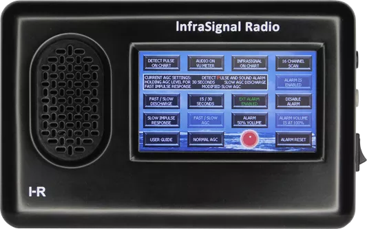
The OPTIONS page is where you set up the AGC (Automatic Gain Control) parameters and:
- Turn the alarm function on / off;
- Set the alarm volume;
- Check the connectivity of the optional remote alarm;
- Turn the remote alarm on / off;
- Run the alarm test;
- Run the scan 16 test signal test;
- Run the sinewave test;
- Run the frequency measurement test;
- Calibrate the LCD;
- Select language, English or Spanish;
- Reset system default settings;
- Read the user’s guide and the radio’s Serial Number.
CURRENT AGC SETTINGS, [window] This window displays the current AGC settings. This window also displays the text, DETECT PULSE AND SOUND ALARM when the detect pulse option is turned on.
NORMAL AGC, [button] Is slow everything. This is the setting for all general monitoring of infrasignals. NORMAL AGC also turns off the DETECT PULSE option.
FAST IMPULSE RESPONSE, [button and in window] This setting provides a faster response to a strong signal when it is first detected. This is a good setting to use when the signal is strong and intermittent.
SLOW IMPULSE RESPONSE, [button and in window] Is the normal setting.
DETECT PULSE, [button] Detect pulse is a special function designed specifically for use with the EMP sensor. It turns on an alarm function that responds to a fast pulse, sounds the alarm and saves the event to memory. In the event that power is lost during or after the pulse is detected, both events are saved to memory. When power is restored, (perhaps with a generator or backup battery) the alarm will sound and a message (in red letters) will appear on screen, saying “A pulse was detected before loss of power”. To protect this message from accidentally being reset, a special reset sequence is provided in the message.
FAST / SLOW DISCHARGE, [button and in window] This setting determines the rate of AGC discharge once the input signal decreases.
HOLD AGC LEVEL, [button] This setting delays the discharge function for a selectable amount of time determined by the 15 / 30 SECONDS setting.
15 / 30 SECONDS, [button] This setting determines the amount of time the HOLD AGC LEVEL holds the AGC level before allowing it to discharge.
FAST / SLOW AGC, [button] This setting determines the overall response of the AGC function. Slow AGC is normal and is modifiable by the other settings. Fast AGC disables all other AGC touch buttons except NORMAL AGC. *Fast AGC is only fast from an infrasignal point of view. It is very slow when compared to other higher frequency receiving equipment.
Transparent (ALARM IS ENABLED), [button] The alarm is turned on for all modes except the AUDIO ON VU METER, FREQUENCY MEASUREMENT and scope speeds 3 and 4.
ENABLE ALARM, [button] The alarm is presently turned off.
Transparent (ALARM IS DISABLED), [button] The alarm is presently turned off.
DISABLE ALARM, [button] The alarm is turned on for all modes except the AUDIO ON VU METER, FREQUENCY MEASUREMENT and scope speeds 3 and 4.
ALARM TEST, [button] When this button is touched, four things happen. The alarm will sound, the red light will flash, the ESPANOL button will change to ALARM 50% VOLUME and the SCAN 16 TEST SIGNAL button will change to a transparent (ALARM VOLUME IS AT 100%). While the alarm is sounding, the volume can be changed to 50% and back to 100% if desired. When the radio is turned off, then turned back on, the alarm volume setting will return to its default value, 100%.
RESERVED FOR EXTERNAL ALARM, [small window] When an optional alarm device is connected, this window will change to a button and display green text, EXT ALARM ENABLED. This is the default setting when the power is first turned on and the external alarm is connected. When the local alarm sounds, the external alarm will also sound. Touch the green EXT ALARM ENABLED button, it will change to display yellow text EXT ALARM DISABLED.
EXT ALARM DISABLED, [button] When the local alarm sounds, the external alarm will not sound.
USER GUIDE, [button] The user guide is written in both English and Spanish. It explains the use of all touch buttons used in the InfraSignal Radio. The user guide also provides step by step instructions for the 2 system level tests, i.e., SCAN 16 TEST INSTRUCTIONS and SINE WAVE TEST INSTRUCTIONS. Additional information such as FCC Part 15 test results, Patent status, Copyright information, Model number, Serial number, software versions and firmware version can be found on page 14 of the English language version only.
ESPANOL / ENGLISH, [button] This is the button to touch to switch languages from English to Spanish and vice versa. In addition to switching between two different languages, this button also resets adjustments, AGC settings, alarm activation and non-volatile memory to default values. This is very handy to reset the system when you want to return to default values. Switch to the other language, then switch back.
LCD CALIBRATION, [button] If you touch one button and an adjacent button response, chances are, the touch screen needs to be recalibrated. This doesn’t happen very often, almost never, but when it does, touch the LCD CALIBRATION button and follow the on-screen instructions.
There are a lot of select-able AGC settings when using the infrasignal modes, most of which will never be needed by most setups. Most of these AGC settings are designed to optimize reception performance for tape or digital recordings. An example would be when trying to record a strong signal that occurs in burst with long pauses (thinking elephants here). You would set the AGC by touching the FAST IMPULSE RESPONSE >> HOLD AGC LEVEL >> 15 / 30 SECONDS buttons to hold for about 15 seconds. Touch the 15 / 30 SECONDS button again to hold for about 30 seconds. You can monitor the signal by going to INFRASIGNAL ON CHART or the INFRASIGNAL ON SCOPE button. If the first strong signal burst is long enough in time, it will level off the AGC to the proper level so the next burst will be received with little or no distortion. If the first strong signal burst is not long enough in time, the AGC will hold a lower value but subsequent burst will add to that value until it reaches the proper level. This is assuming that the strong signal burst occur before the selected hold time runs out. If the hold time runs out and the AGC starts to discharge, the next strong burst will start to increase the AGC from that discharged point.